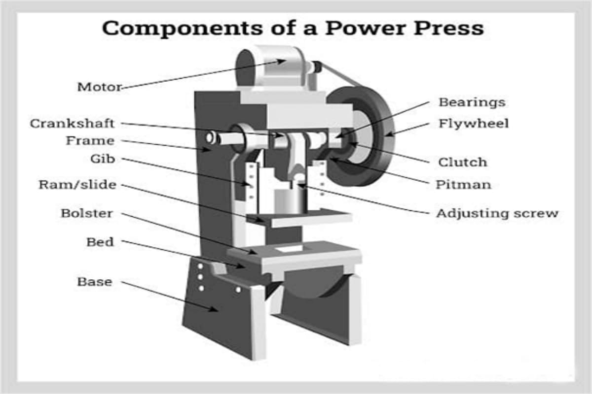
A press machine, also known as a forming press, is a heavy industrial machine that uses pressure to change or adjust the size of the workpiece like the steel, aluminum, or other materials. Press machines play a pivotal role in the sheet metal manufacturing industry. They are also known as forming presses or mechanical presses. Once a workpiece has been designed, operators use press machines to manufacture it. These machines work by applying pressure to bend and press the sheet metal. A press machine consists of a frame and base, and it is equipped with punches and dies, which are located on the ram and workbench, respectively. The machine applies pressure to the metal plate through a power device that drives the punch. Press machines come in various types, including hydraulic, pneumatic, and mechanical, and are differentiated based on their power system, capacity, and other factors. Different press machines operate through different dynamic mechanisms, and their design structure may include C-frame presses and screw presses. There are numerous press manufacturing processes, such as die cutting, forging, and stamping. In this article, we will explore the definition of press machines and their various types. The driving system of a power press machine is a crucial component that powers the machine's operations. In a hydraulic press machine, the ram movement is driven by the hydraulic cylinder and the piston rod, which are typically located on both sides of the press machine. The hydraulic system is capable of sustaining large loads and longer strokes continuously. The mechanical drive system, on the other hand, consists of components such as a crank, flywheel, eccentric, and knuckle joint. The flywheel rotates, connecting the crank to drive the movement of the ram, providing a strong mechanical driving force, which is ideal for blanking and stamping processes. A pneumatic press machine operates on compressed air, and its structure is relatively simple. The power comes from the movement of compressed air, making it fast and capable of quickly driving the ram. In conclusion, each type of driving system has its own strengths and is suitable for different metalworking processes. Press machines can be classified by different standards, including mechanical (hydraulic, pneumatic, etc.) and stamping (forging, punching, etc.). A manual press machine is operated manually by the operator, who applies pressure to the machine through a handle. After the handle is rotated, the ram moves up and down, generating force through the lever to drive the punch to make a linear motion. The hydraulic cylinder generates high pressure and slowly drives all components of the punch and die process of the workpiece. The manual press machine is suitable for small batches and simple production and can be used for bending, blanking, and punching. The structure of the whole machine is very simple, including a C-frame, punch, die, handle, and guide rail. The larger the opening of the C-shaped frame, the better the feeding of metal plates. It has an independent hydraulic system, which has the features of small volume and low operating cost. The manual press machine is very slow and suitable for one-time and light operation. Manual presses are commonly used for laboratory sample preparation, small-scale production, and repair work. They are suitable for metal stamping, marking, riveting, forming, and bending operations. Hydraulic press machine drives the ram through a series of hydraulic system components, with the oil cylinder usually installed on the top beam. The speed of the ram is determined by the circuit flow and oil quantity of the hydraulic system. A hydraulic press operates based on Pascal's law, which states that pressure applied to a confined fluid is transmitted equally in all directions. Hydraulic presses typically consist of two pistons of different sizes. The fluid (usually oil) is pressurized in the smaller piston and then transmitted through pipes to the larger piston, generating a greater force. By installing different punches and dies, the machine can work. To ensure operator safety, the hydraulic press machine is equipped with sensing devices and safety switches. With larger capacity, longer stroke, and adjustable tonnage, the hydraulic press machine is more suitable for manufacturing complex workpieces. Hydraulic presses are widely used in metal forming, forging, stamping, punching, mould manufacturing, deep drawing, die casting, and other sheet metal processes. They are also used for crushing cars, making cocoa powder, automotive parts manufacturing, the aerospace industry, and sword making. Mechanical press machines use mechanical energy to process sheet metal and come in various types. The power source of the mechanical press machine is the motor, which transfers energy to the ram. Compared to hydraulic press machines, mechanical press machines have a faster speed and are suitable for stamping. A mechanical press operates by using an electric motor to drive a flywheel, which stores kinetic energy. This energy is then transferred through a clutch and crank mechanism, converting rotational motion into linear motion to drive the ram and apply pressure to the workpiece. They are characterized by the rapid and repeated application of pressure within a limited stroke. However, the stroke of the mechanical press machine is unstable because force is applied at different speeds, making it unsuitable for manufacturing complex workpieces. Currently, the press capacity of the mechanical press machine can reach 12,000 tons. Mechanical press machines provide fast and repeatable operations, reducing the cost of mass production. Mechanical presses are commonly used for metal stamping, forming, and extrusion operations, suitable for mass production. They are widely used in electronics, industrial manufacturing, automotive parts, construction, and aerospace industries. A pneumatic press machine is powered by compressed gas, which is compressed and expanded to increase the pressure in the cylinder. The pressure in the pneumatic press machine is consistent throughout the entire stroke, and there is no need to adjust the pressure. The machine moves quickly and can carry out multiple cycles rapidly. The maximum force of the pneumatic press machine is determined by the cylinder aperture and the regulated working pressure. During use, the pneumatic press machine must maintain the operating pressure; otherwise, the stroke of the press will be intermittent, which is not conducive to process monitoring. To prevent air supply failure, pneumatic check valves and shaft locking devices are required to ensure stroke accuracy and operator safety. (2) Application Scenarios Pneumatic presses are widely used for bending, stamping, forming, and cutting metal sheets. They are used in automotive manufacturing, metalworking, and electronics manufacturing industries. A Punching Press Machine, also known as a punch press or punching machine, operates by shearing and deforming materials. It uses force generated by mechanical, hydraulic, or pneumatic systems to drive a punch into the workpiece, creating holes or specific shapes in metal sheets or other materials. The basic components of a punching press include the frame, bed, punch, die, and power source. Punching machines have punches and dies of different sizes and shapes. During processing, the plate is placed under the punch, and the pressure of the machine causes the punch to move downward. The punching press machine has two types: C-frame and H-frame. The C-frame drives the ram through the hydraulic cylinder to operate the punch, while the H-frame is designed to place the metal plate in the center of the machine without protruding. The C-shaped frame occupies less space and is flexible to use, while the H-frame is suitable for large-scale manufacturing. The forming technology of the punching press includes blanking, punching, perforating, and bending. Punching presses are widely used in the automotive, aerospace, electronics, and construction industries. They are used to manufacture automotive parts, electronic device enclosures, building metal structures, metal frames, and brackets. Punching presses can also be adapted for custom applications, meeting unique needs in industries such as furniture and signage. The stamping press machine forms metal sheets by applying pressure on them. It features interlocking punch and work table devices that secure the plate for cutting or punching into the final shape. Due to its large size and complex operation, it requires a great amount of power for driving. The surface of the workpiece produced by the stamping press machine may have defects, and the punching holes may not be clean enough. The stamping machine only forms the metal sheet and may not handle details well. Stamping presses are widely used in the automotive manufacturing, electronics, household appliances, construction, and aerospace industries. They are used to produce automotive body parts, electronic device enclosures, household appliance components, and building metal structures. In the ever-evolving world of manufacturing, choosing the right press machine is paramount for any operation’s success. The press machine is widely used in the sheet metal processing industry and has powerful functions. The press machine can be used for cutting, bending, stamping, forming, and other metal processing. It is necessary to understand the function and use of the press machines before making a choice. Selecting an inappropriate press machine leads to a waste of resources and low machine efficiency. Today, many mechanical and hydraulic press machines are being enhanced with computer numerical control (CNC) systems. Press machines are essential in the sheet metal industry, as they can perform various metal processing tasks such as cutting, bending, stamping, and forming. The most effective machines for workpiece bending are press brakes and panel benders. These industrial processing machines have been around for decades and continue to be popular. With 20 years of professional experience in sheet metal machine production, ADH offers a wide range of products, including press brakes, panel benders, laser cutting machines, and shearing machines. Our sales team can help you select the right machine that meets your needs while ensuring the most cost-effective solution. Browse our products or contact our sales team to learn more about our products and their pricing. Custom Caps,Custom Logo 6-Panel Cap,Embroidered Logo Cap,Duck Tongue Cap Topwell Crafts Co., Ltd , https://www.topwellmetal.comI. Introduction of Press Machine
II. The Driving System of the Power Press Machine
III. Type of Machine Press
1. Manual Press Machine
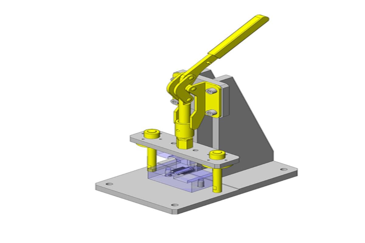
(1) Working Principle
(2) Application Scenarios
(3) Advantages
(4) Disadvantages
(5) Technical Specifications
Specification Value Force 630 kN to 10,000 kN Weight 11 kg to 250 kg Nominal Force 30 tons Power Source Hydraulic Table Length 1100 mm to 1300 mm Max Pressure 0 bar to 1 bar Overall Length 3300 mm Applications Marking, numbering, identifying, crimping, riveting, punching 2. Hydraulic Press Machine
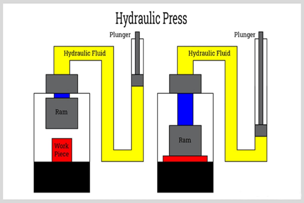
(1) Working Principle
(2) Application Scenarios
(3) Advantages
(4) Disadvantages
(5) Technical Specifications
Specification Value Capacity 600 tons Height 5300 mm (+/-100 mm) Width 1500 mm (+/- 100 mm) Table Area (Width) 3000-5000 mm Table Area (Height/Length) 1200 - 1500 mm Minimum Work Capacity 1150 mm Distance Between Trays (Max) 2300 mm Piston Stroke (Min) 500 mm Pump 500-90 1/min Tank Capacity (Min) 670 L Type C-Type Travel Speed (Max) Approach: 18 mm/sec
Working: 5 mm/sec
Backward:20 mm/secIntegrated Crane Capacity Min 3 Ton at 2 meters Travel Speed (Crane) Free: 80 mm/s
Under Load: 5 mm/sControls Manual with remote control Stroke/Pressure Adjustable Instrumentation Analogue & digital Electrical Supply 3¢, 415 V, 50Hz Safety Features Mesh Guarding, Interlocked light guards, Safety valve, Auto stop Warranty Min 12 months Installation and Commissioning By the firm 3. Mechanical Press Machine
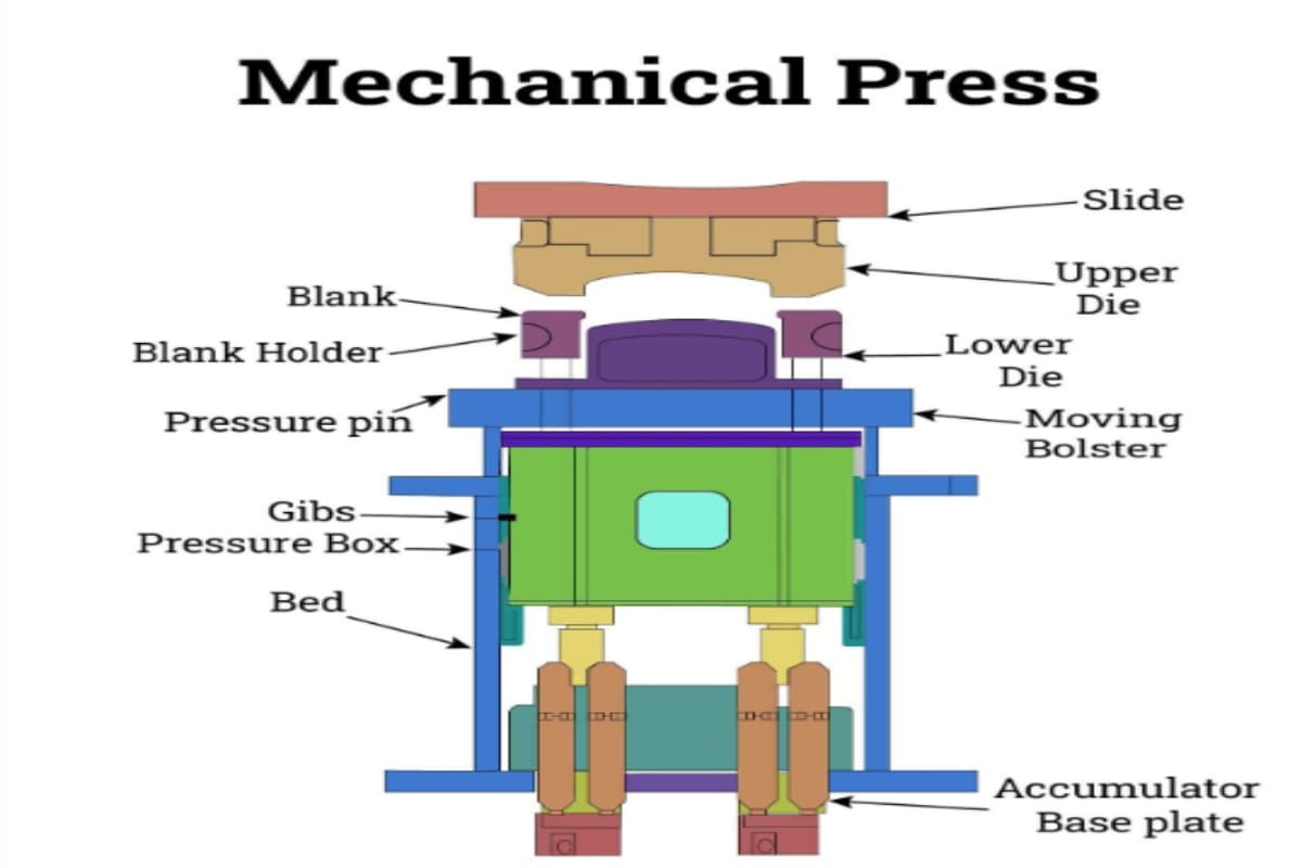
(1) Working Principle
(2) Application Scenarios
(3) Advantages
(4) Disadvantages
(5) Technical Specifications
Specification Value Pressure Force 200 tons Motor Power 15 kW Throat Depth 400 mm Strokes per Minute 40 spm Stroke Adjustment 20 - 170 mm Max. Closed Mould Height 430 mm Distance Between Table and Ram 600 mm Ram Adjustment 80 mm Table Size 800 ×1200 mm Ram Size 400 ×700 mm Table Height 950 mm Ø Hole in the Table 300 mm Ø Hole in the Ram 60 mm Total Width (Frontal) 2130 mm Total Length 2100 mm Overall Height 3250 mm Features Central motorized lubrication, hydraulic overload protection, electro-pneumatic clutch and brake, safety light guards, PLC control, adjustable stroke, anti-vibration pads Optional Accessories Inverter, pneumatic/hydraulic die ejector, lower auxiliary table, strain gauge system, NC digital display 4. Pneumatic Press Machine
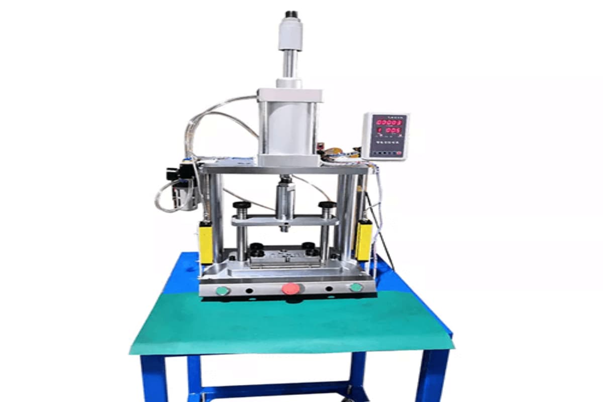
(1) Working Principle
(3) Advantages
(4) Disadvantages
(5) Technical Specifications
Specification Value Capacity 5 tons to 250 tons Frame Fabricated steel construction Pneumatic Clutch Brake Linked with flywheel Crank Shaft High tensile steel Bearings High-grade gunmetal Ram High tensile cast iron/steel Stroke Adjustment Adjustable Flywheel High-grade Cl Power Supply 400/440 Volts,3 Phase,50 Cycles Stroke Per Minute 30 to 70 spm Electric Motor 1 HP to 25 HP Air Pressure 5.5 kg/cm2 5. Punching Press Machine
(1) Working Principle
(2) Application Scenarios
(3) Advantages
(4) Disadvantages
(5) Technical Specifications
Specification Value Force Exerted by Ram Varies (e.g., 30 tons) Stroke Length Adjustable Ram Adjustment Range Adjustable Worktable Dimensions Varies Speed (Strokes per Minute) Varies Power Consumption Varies Flywheel Drive Stable power consumption, cost-effective, easy maintenance Mechanical Drive Consistent force,durable,reliable Hydraulic Drive Precision control,suitable for varied tasks 6. Stamping Press Machine
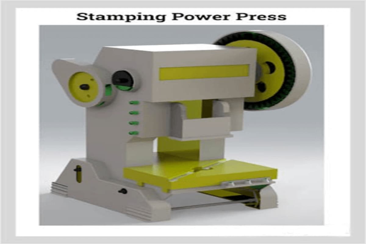
(1) Working Principle
(2) Application Scenarios
(3) Advantages
(4) Disadvantages
(5) Technical Specifications
Specification Value Capacity 3000 kN (300 tons) to 5000 kN (500 tons) Stroke Length 250 mm to 300 mm Strokes per Minute (No Load) 15 to 40 spm Die Height 570 mm to 650 mm Slide Area (LR x FB) 1000 x 900 mm to 1200 ×1100 mm Bolster Area (LR x FB) 1000 × 985 mm to 1200 x1215 mm Rated Tonnage Point Above BDC 13 mm Slide Knockout Capacity 30 kN to 50 kN Die Cushion Capacity 160 kN to 260 kN Hydraulic Overload Protection Included Control System PLC Safety Features Lateral protection screens,safety light guards IV. Precautions When Selecting A Press Machine
V. Conclusion
Types of Press Machines: A Comprehensive Guide